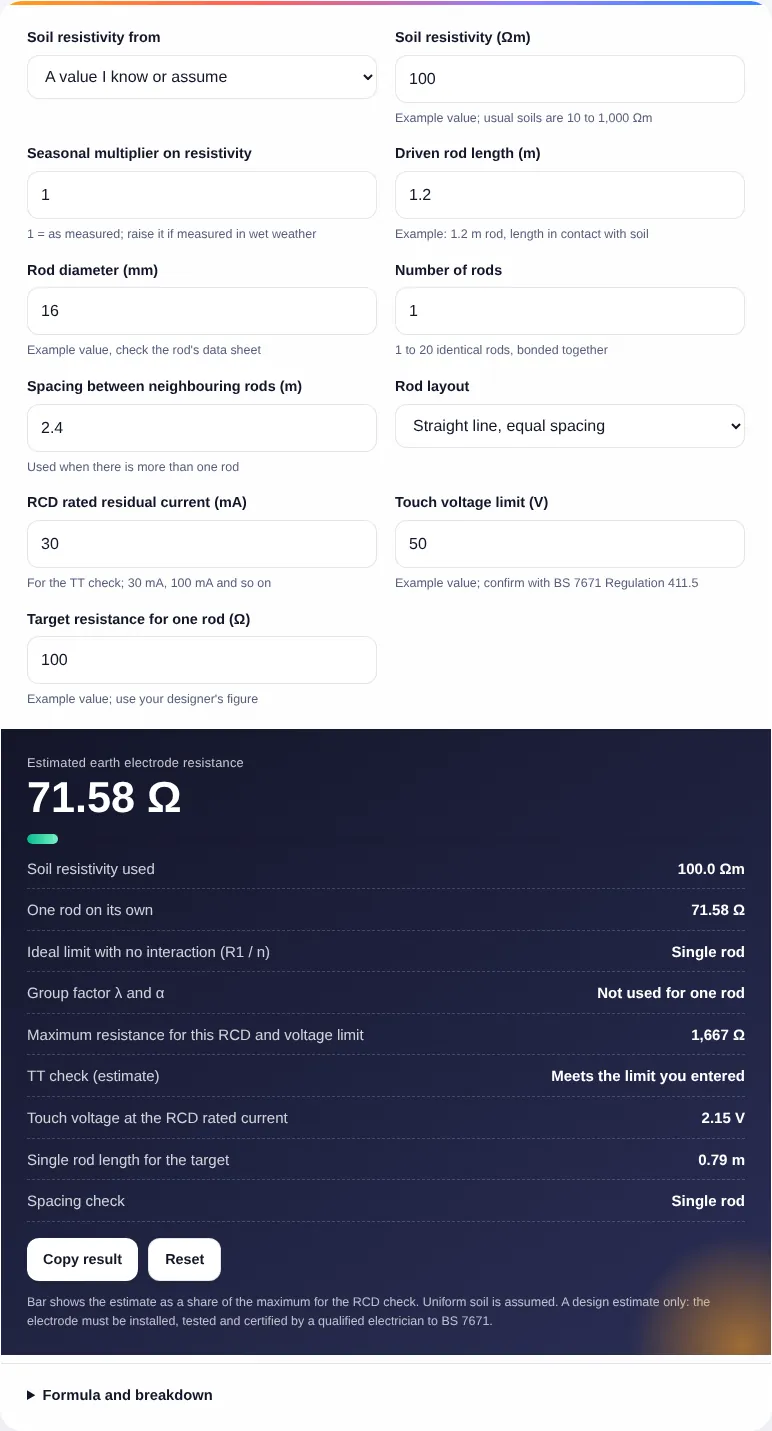
Bar shows the estimate as a share of the maximum for the RCD check. Uniform soil is assumed. A design estimate only: the electrode must be installed, tested and certified by a qualified electrician to BS 7671.
Formula and breakdown
n/a
n/a
n/a
n/a
This earth rod resistance calculator estimates the resistance to earth of one driven rod or a group of bonded rods from soil resistivity, rod length and diameter, for electricians, designers and students working on TT installations, outbuildings, EV chargers and solar systems in the UK and Europe. It also checks the result against an RCD and touch voltage limit you enter, and works out how long a single rod would need to be.
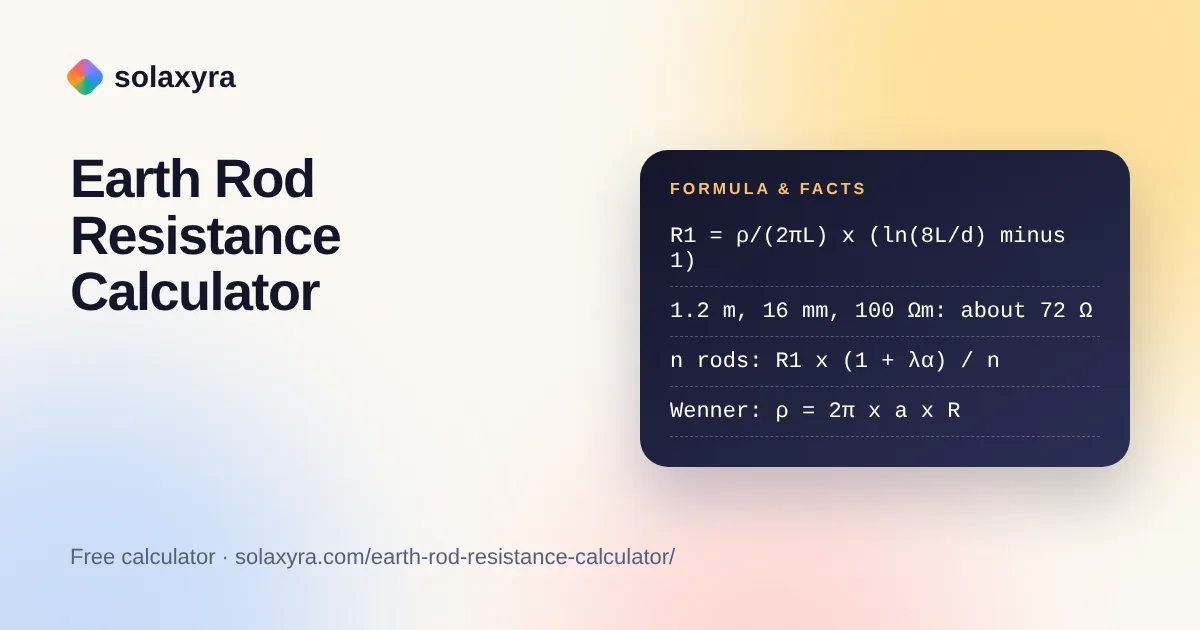
Quick answer: An earth rod resistance calculator uses R = ρ / (2πL) x (ln(8L / d) minus 1). A 1.2 m rod of 16 mm diameter in 100 Ωm soil gives about 72 Ω, and a 2.4 m rod about 40 Ω. Extra rods lower resistance only when spaced at least their length apart.
What Is an Earth Rod Resistance Calculator?
An earth rod resistance calculator is a tool that predicts the resistance in ohms between a driven earth electrode and the general mass of earth, before the rod is installed and tested. In plain words: resistance equals soil resistivity divided by 2π times the rod length, multiplied by the natural logarithm of 8 times the length over the diameter, minus 1. Long rods in wet, low-resistivity ground give low values; short rods in dry sand or rock give high ones.
The IET’s guidance on inspection and testing of earth electrodes gives this formula for a single vertically driven rod and warns that it can only give an approximate value. The same article points to BS 7430:2011+A1:2015, the code of practice for protective earthing, for UK soil resistivity data.
How Do You Use the Earth Rod Resistance Calculator?
- Enter the soil resistivity in Ωm, or switch to “Wenner four-pin test reading” and enter the pin spacing and the reading from your tester.
- If the soil was measured in wet weather, raise the seasonal multiplier to allow for drier or colder months.
- Enter the driven length of the rod in metres and its diameter in millimetres.
- For more than one rod, enter the number of rods, the spacing between neighbours and whether they stand in a line or a ring.
- Enter the RCD’s rated residual current and the touch voltage limit that applies to your installation, then a target resistance if you want the rod length solver.
- Read the estimate, the single rod value, the TT check and the breakdown, then confirm on site with an earth electrode test.
What Is the Formula for Earth Rod Resistance?
The resistance of one vertical rod is R1 = ρ / (2πL) x (ln(8L / d) minus 1), where ρ is soil resistivity in Ωm, L the driven length in metres and d the rod diameter in metres. Resistance falls almost in proportion to length but only slowly with diameter, which is why the IET article notes that length has far more effect than diameter.
The table shows single rod values from the formula for a 16 mm rod. The resistivity columns are examples spanning the usual 10 to 1,000 Ωm range given in the Wikipedia article on soil resistivity; your own soil may sit anywhere in that range or outside it.
| Driven length | 10 Ωm | 50 Ωm | 100 Ωm | 300 Ωm | 1,000 Ωm |
|---|---|---|---|---|---|
| 1.2 m | 7.2 Ω | 35.8 Ω | 71.6 Ω | 214.7 Ω | 715.8 Ω |
| 2.4 m | 4.0 Ω | 20.2 Ω | 40.4 Ω | 121.2 Ω | 403.9 Ω |
| 3.6 m | 2.9 Ω | 14.4 Ω | 28.7 Ω | 86.1 Ω | 287.2 Ω |
| 6.0 m | 1.9 Ω | 9.3 Ω | 18.6 Ω | 55.8 Ω | 185.8 Ω |
Diameter barely matters: at 1.2 m in 100 Ωm soil, a 12.7 mm rod gives 74.6 Ω and a 25 mm rod 65.7 Ω. Driving one rod deeper, or coupling extension rods, is usually the most effective first step.
How Much Do Extra Earth Rods Reduce Resistance?
Two 1.2 m rods spaced 2.4 m apart in 100 Ωm soil give about 55% of the single rod value, not 50%, because each rod raises the ground potential around its neighbour. The earth rod resistance calculator handles this with the group formula R = R1 x (1 + λα) / n, where n is the number of rods, α = ρ / (2π x R1 x s) with s the spacing, and λ is the sum of s divided by the distance to every other rod, averaged over the rods.
The λ factor here is worked out from the layout you choose, treating each rod as a point source of current at a distance; it is not copied from a published table. The DEHN Lightning Protection Guide makes the same practical point: rods should be spaced at least their driven depth apart, and the real total resistance is higher than a simple parallel calculation suggests. Values for 1.2 m, 16 mm rods in 100 Ωm soil at 2.4 m spacing:
| Rods in a straight line | λ (line) | λ (ring) | Estimate, line | Ideal R1 / n |
|---|---|---|---|---|
| 1 | n/a | n/a | 71.6 Ω | 71.6 Ω |
| 2 | 1.000 | 1.000 | 39.1 Ω | 35.8 Ω |
| 3 | 1.667 | 2.000 | 27.5 Ω | 23.9 Ω |
| 4 | 2.167 | 2.707 | 21.5 Ω | 17.9 Ω |
| 6 | 2.900 | 3.655 | 15.1 Ω | 11.9 Ω |
| 10 | 3.858 | 4.774 | 9.7 Ω | 7.2 Ω |
A ring has a higher λ than a line with the same neighbour spacing because the rods sit closer to each other on average, so a line of rods is slightly more effective for the same number and spacing.
What Earth Rod Resistance Do You Need for a TT System?
In a TT system the earth rod resistance, multiplied by the RCD’s rated residual current, must keep the touch voltage on exposed metalwork within the limit set by BS 7671. The earth rod resistance calculator divides the touch voltage limit you enter by the RCD current: with the example 50 V limit and a 30 mA RCD, the maximum is 50 / 0.03 = 1,667 Ω. The Wikipedia article on earthing systems describes a safe threshold of about 50 V AC, but the limit that applies to your installation must be taken from BS 7671 Regulation 411.5 and Table 41.5, which is why it is an input.
Meeting the theoretical maximum is not the same as a good electrode. Soil dries, freezes and corrodes the rod over the years, so designers usually aim well below the limit and record the measured value on the certificate. The earth rod resistance calculator shows the touch voltage at the RCD rated current so you can see the margin. For the wider protective device check, the earth loop impedance calculator covers Zs, and the Ohm’s law calculator shows the V = I x R step behind the touch voltage.
How Is Soil Resistivity Measured?
Soil resistivity is usually measured with the Wenner four-pin method: four pins are driven in a straight line at equal spacing a, current passes between the outer pair and the tester reads a resistance R between the inner pair, giving ρ = 2π x a x R. The earth rod resistance calculator converts that reading for you; a 2 m spacing and a reading of 12 Ω give about 151 Ωm.
Resistivity changes with moisture, salt content and temperature, so a reading taken after rain can be far lower than the summer or frozen winter value. Wikipedia’s soil resistivity article notes that in very cold regions a winter value of 5 to 6 times the summer value is a reasonable average when no other data is available. Use the seasonal multiplier to test how sensitive your design is.
Who Can Install and Test an Earth Rod in the UK?
An earth electrode is part of the fixed electrical installation, so it must be designed, installed, inspected, tested and certified by a qualified electrician to BS 7671. In England, domestic work also falls under Part P of the Building Regulations, explained in Approved Document P, and Wales has its own equivalent. The earth rod resistance calculator gives a design estimate; the value that counts is the one measured on site with an earth electrode tester, for example by the fall of potential method the IET describes.
Never disconnect an existing earth to test it while the installation is live, and do not drive rods where buried cables, gas or water pipes may run. If a rod is for solar, battery or EV charging equipment, the installer’s design should also cover the earthing arrangement of that equipment; see the solar cable size calculator for the DC wiring side.
Worked Example: Three Rods at a Rural Workshop
Example: a designer plans a TT supply for a detached workshop. A Wenner test with 2 m pin spacing reads 12 Ω. They plan three 2.4 m rods of 16 mm diameter in a straight line, 2.4 m apart, protected by a 30 mA RCD, with an example touch voltage limit of 50 V. All figures are examples, not measurements from a real site.
- Soil resistivity: 2 x π x 2 x 12 = 150.8 Ωm.
- One rod: 150.8 / (2π x 2.4) x (ln(8 x 2.4 / 0.016) minus 1) = 10.0 x 6.09 = 60.9 Ω.
- α = 150.8 / (2π x 60.9 x 2.4) = 0.164. λ for three rods in a line = 1.667.
- Group: 60.9 x (1 + 1.667 x 0.164) / 3 = 25.9 Ω, against an ideal 20.3 Ω.
- Check: maximum 50 / 0.03 = 1,667 Ω. Touch voltage at 30 mA = 25.9 x 0.03 = 0.78 V.
The earth rod resistance calculator shows the same values. The estimate leaves a wide margin, but the electrician must still measure the installed electrode and record the result.
Frequently Asked Questions
How do you calculate earth rod resistance?
Use R = ρ / (2πL) x (ln(8L / d) minus 1), with soil resistivity ρ in Ωm, driven length L and diameter d in metres. A 1.2 m rod of 16 mm diameter in 100 Ωm soil gives about 72 Ω. The result is an approximation; only an on-site test gives the real value.
Does a longer or thicker earth rod reduce resistance more?
Length has far more effect. At 100 Ωm, a 16 mm rod falls from about 72 Ω at 1.2 m to about 40 Ω at 2.4 m, while increasing the diameter from 12.7 mm to 25 mm at 1.2 m only moves it from about 75 Ω to 66 Ω.
How far apart should earth rods be?
At least the driven length of the rods, as manufacturers such as DEHN advise. Closer rods share the same ground and screen each other, so adding them achieves little. The calculator warns when spacing is less than the rod length and shows how far the result is from the ideal R1 divided by n.
What is the maximum earth electrode resistance with a 30 mA RCD?
Dividing a 50 V touch voltage limit by 0.03 A gives 1,667 Ω, which is the figure this calculator shows with its example inputs. Confirm the limit and method that apply to your installation in BS 7671 Regulation 411.5 and Table 41.5, and aim well below it for long-term stability.
What soil resistivity should I use?
Use a measured value from a Wenner four-pin test where you can. Usual soils range from about 10 to 1,000 Ωm, with exceptional values from 1 to 10,000 Ωm. Without a measurement, run the calculator at a high and a low value to see the possible spread.
Is the earth rod resistance calculator result good enough for certification?
No. It is a design estimate based on uniform soil. The installed electrode must be tested by a qualified electrician with an earth electrode or loop tester, and the measured value recorded on the certificate to BS 7671. In England, Part P of the Building Regulations also applies to domestic work.
Checked October 2026 by the Solaxyra Editorial Team. Sources: IET: Inspection and testing of earth electrodes, Wikipedia: Soil resistivity, Wikipedia: Earthing system, DEHN Lightning Protection Guide, earth electrode section, GOV.UK: Approved Document P.