This guide explains the voltage drop limits that UK electrical installations are designed to, what they mean in volts at 230 V, and how they affect long cable runs to garages, garden buildings and EV chargers, for homeowners, installers and students in Great Britain. The BS 7671 voltage drop limits are short to state, but they interact with the legal supply voltage range in a way most summaries skip.
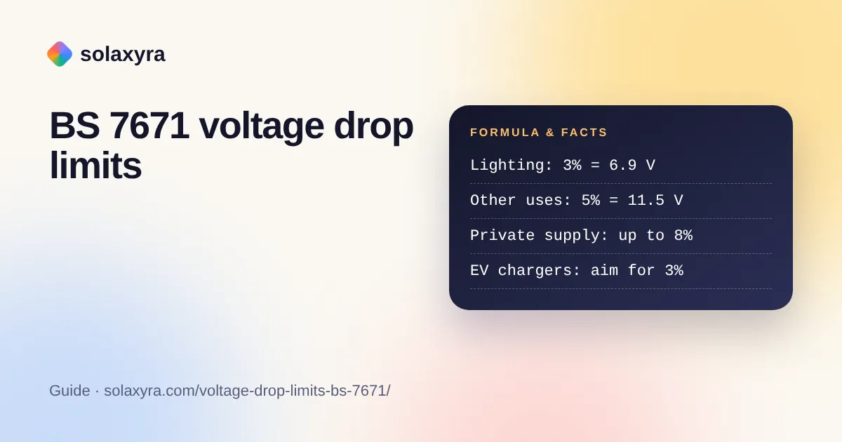
Quick answer: The BS 7671 voltage drop limits for an installation fed from a public supply are 3% for lighting and 5% for other uses, measured from the origin of the installation to the load. At 230 V that is 6.9 V and 11.5 V. Supplies from a private transformer may allow up to 8% for other uses.
What are the BS 7671 voltage drop limits?
BS 7671 recommends a maximum voltage drop of 3% for lighting circuits and 5% for other uses where the installation is supplied from a public low voltage network. These figures sit in Appendix 4 (section 6.4, Table 4Ab) of BS 7671, the IET Wiring Regulations. They are measured between the origin of the installation (the supply terminals, normally at the meter) and the point where the equipment is connected, so the drop in any sub-main counts as well as the drop in the final circuit.
| Type of supply | Lighting | Other uses | Other uses in volts at 230 V |
|---|---|---|---|
| Public low voltage supply (most homes) | 3% (6.9 V) | 5% (11.5 V) | 11.5 V |
| Private supply from your own transformer | Higher than 3% (see Table 4Ab) | 8% | 18.4 V |
The private supply figure is quoted in the IET article listed below. A private supply usually means a site with its own transformer, such as a large commercial or farm installation, not an ordinary house.
The BS 7671 voltage drop limits are recommendations. The underlying rule in Section 525 of BS 7671 is that the voltage at equipment must be suitable for that equipment; designing within the Appendix 4 figures is the normal way an electrician shows this.
Why does the supply voltage range matter for voltage drop?
The BS 7671 voltage drop limits are worked from the nominal 230 V, but the real supply can legally be as low as 216.2 V, so the voltage at an appliance can end up well below 230 V minus 11.5 V. Regulation 27 of the Electricity Safety, Quality and Continuity Regulations 2002 declares UK low voltage supplies at 230 V with a permitted variation of 10% above and 6% below, which is 216.2 V to 253 V.
Put the two together and the worst case for a non-lighting circuit is 216.2 V at the origin minus 11.5 V in the cables, about 204.7 V at the equipment. Most household equipment copes with that. Some does not, and EV charge points are the clearest example.
How does voltage drop affect EV chargers?
Many EV charge points contain an open PEN detection device that disconnects the car if the voltage leaves a set window, so a cable that meets the 5% limit can still cause nuisance tripping on a low supply. The IET’s Wiring Matters article from July 2023 explains that such a device must disconnect within 5 seconds if the voltage is outside 207 V to 253 V.
The article’s own arithmetic shows the problem: 216.2 V minus a 5% drop of 11.5 V gives 204.7 V, which is below 207 V. It recommends limiting voltage drop on these circuits to 3%, tighter than the 5% that the BS 7671 voltage drop limits allow for other uses. At 3%, the worst case is 216.2 V minus 6.9 V, or 209.3 V, which stays inside the window.
Example: a 32 A (7.4 kW) charge point at the end of a 25 m run. With 6 mm² copper cable, an approximate calculation (method below) gives a drop of about 5.4 V, or 2.3%, leaving about 210.8 V at the charger on a 216.2 V supply. With 10 mm² cable the drop falls to about 3.2 V, or 1.4%, leaving about 213.0 V. Both pass, but the larger cable gives more margin if the run is longer or the supply is weak. The final design must use the BS 7671 tables and be done by a qualified electrician.
How is voltage drop calculated under BS 7671?
Voltage drop in volts equals the cable’s tabulated millivolts per amp per metre (mV/A/m), multiplied by the design current in amps and the cable length in metres, divided by 1,000. BS 7671 Appendix 4 lists mV/A/m values for each cable type and size. The steps for checking a circuit against the BS 7671 voltage drop limits are:
- Work out the design current (Ib) of the circuit from the load, for example 7.4 kW ÷ 230 V = about 32 A.
- Measure the route length of the cable from the consumer unit (or sub-main origin) to the load, in metres.
- Look up the mV/A/m value for the cable type, size and installation method in BS 7671 Appendix 4.
- Multiply: mV/A/m × Ib × length ÷ 1,000 = volts dropped.
- Add the drop in any sub-main feeding the circuit.
- Divide the total by 230 and multiply by 100 to get a percentage, then compare with 3% or 5%.
The voltage drop calculator carries out these steps for single-phase, three-phase and DC circuits. To turn an appliance’s kW into design current first, use the kW to amps calculator.
Where do mV/A/m figures come from?
An mV/A/m figure is essentially the resistance of the outgoing and return conductors per metre, at their working temperature, expressed in millivolts per amp. You can approximate it from physics: copper has a resistivity of 1.68 × 10⁻⁸ ohm metre at 20 °C and a temperature coefficient of about 0.00404 per kelvin, according to the resistivity table. For a two-conductor single-phase circuit, mV/A/m ≈ 2 × resistivity ÷ area × 1,000.
The table shows that approximation at 20 °C and at an example working temperature of 70 °C, with approximate maximum run lengths at full design current. The published BS 7671 values are somewhat higher than these physics estimates, so real maximum lengths are shorter. Treat this table as a guide to scale only.
| Copper size | Approx. mV/A/m at 20 °C | Approx. mV/A/m at 70 °C | Example circuit | Approx. max length at the limit |
|---|---|---|---|---|
| 1.5 mm² | 22.4 | 26.9 | Lighting at 6 A, 3% | About 43 m |
| 2.5 mm² | 13.4 | 16.2 | 20 A radial, 5% | About 36 m |
| 4 mm² | 8.4 | 10.1 | 32 A radial, 5% | About 36 m |
| 6 mm² | 5.6 | 6.7 | 32 A EV charger, 3% | About 32 m |
| 10 mm² | 3.4 | 4.0 | 32 A EV charger, 3% | About 53 m |
| 10 mm² | 3.4 | 4.0 | 40 A shower, 5% | About 71 m |
Larger cables also have a reactance component that the BS 7671 tables include, so for big sub-mains the simple resistance approximation is not enough. Voltage drop is not the only test either: the cable must also carry the current safely after correction for grouping, insulation and ambient temperature, and the circuit must disconnect fast enough under a fault.
What happens if voltage drop is too high?
Excessive voltage drop wastes energy as heat in the cable, makes lights dim when loads switch on, slows motors and heating, and can make sensitive equipment such as EV chargers or heat pump controls trip or misbehave. The energy lost is the drop multiplied by the current: in the 25 m, 6 mm² charger example above, about 5.4 V × 32 A, or roughly 172 W while charging at full power.
Where an existing circuit is too long to meet the BS 7671 voltage drop limits, the remedies are a larger cable, a shorter route, splitting the load across more circuits, or for very large loads a three-phase supply. Any of these is a change to fixed wiring and must be designed, installed, tested and certified by a qualified electrician to BS 7671, with the work notified under Building Regulations where required. On an existing installation, an electrician can also verify voltage drop by measuring the line and neutral conductor resistance and multiplying by the design current.
Do the same limits apply to solar panels and DC cables?
The BS 7671 voltage drop limits of 3% and 5% in Appendix 4 are written for the AC installation from the origin, not for the DC side of a solar array or a 12 V system, which are designed to the equipment maker’s guidance and good practice. Low-voltage DC systems are much more sensitive, because a 1 V drop is over 8% of 12 V. For DC runs from panels to an inverter or charge controller, the solar cable size calculator lets you choose a target drop and finds the cable size.
Frequently Asked Questions
What is the maximum voltage drop allowed in the UK?
For installations supplied from the public network, BS 7671 recommends no more than 3% for lighting and 5% for other uses, measured from the origin to the load. At 230 V that is 6.9 V and 11.5 V. Private supplies from a site transformer can allow up to 8% for other uses.
Is 5% voltage drop measured from the meter or the consumer unit?
It is measured from the origin of the installation, normally the supply terminals at the meter, to the equipment. So any drop in the meter tails and in a sub-main to a garage or outbuilding consumer unit must be added to the final circuit’s drop.
Why should EV charger circuits use 3% voltage drop?
Open PEN detection in many chargers disconnects outside 207 V to 253 V. With the legal minimum supply of 216.2 V and a 5% drop, the charger could see 204.7 V and trip. The IET’s July 2023 Wiring Matters article therefore recommends limiting the drop to 3%.
Is voltage drop a safety failure on an inspection report?
Excessive voltage drop is usually a performance issue rather than an immediate shock risk, but it can lead to overheating connections or equipment malfunction. An electrician assessing an installation will judge its effect on the connected equipment and recommend improvement where needed.
Can I fix voltage drop myself with a bigger cable?
No. Replacing or extending fixed wiring is notifiable work in many cases and must be designed, installed, tested and certified by a qualified electrician to BS 7671. Cable size also affects fault protection, so changing it without a full design check can make a circuit unsafe.
Checked October 2026 by the Solaxyra Editorial Team. Sources: IET Wiring Matters, July 2023: voltage drop and EV charging open PEN detection, ESQCR 2002 regulation 27, Wikipedia: electrical resistivity and conductivity.