Guidance only. Cable selection must also satisfy current-carrying capacity, fault protection and installation method. In the UK the design must be done or checked by a registered electrician and meet BS 7671; elsewhere follow the local wiring rules.
Formula and breakdown
n/a
This voltage drop calculator works out how many volts are lost along a cable, and what share of the supply that is, for 230 V single-phase, 400 V three-phase and low voltage DC circuits in the UK, Ireland and the rest of Europe. Enter the current, one-way length and conductor size in mm² or AWG, or type in the mV/A/m figure from a cable table, and the tool checks the result against the limit you choose.
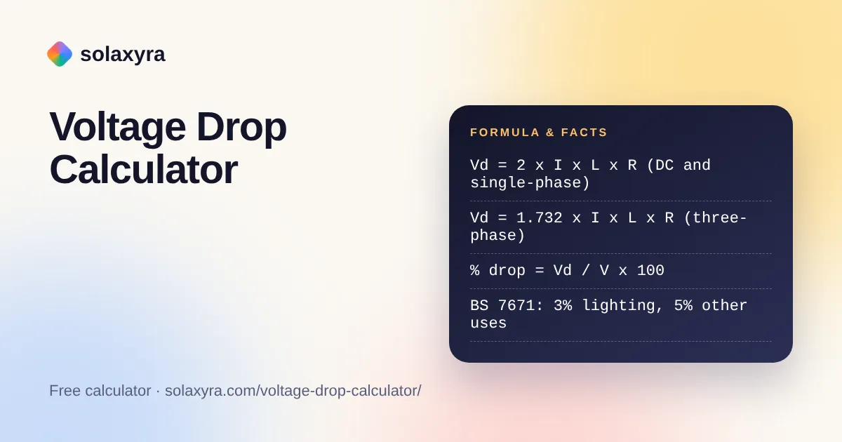
Quick answer: A voltage drop calculator multiplies current, cable resistance per metre and length. For DC and single-phase AC use twice the one-way length; for three-phase use root 3. Divide by supply voltage for a percentage. BS 7671 recommends up to 3% for lighting and 5% for other uses on a public supply.
What Is a Voltage Drop Calculator?
A voltage drop calculator is a tool that estimates the voltage lost to resistance in the conductors between a supply and its load. Every metre of cable has a little resistance, so some voltage becomes heat in the cable instead of reaching the appliance, charger or inverter.
In plain words, the formula is: voltage drop equals current, times resistance per metre, times length, times a circuit factor. The factor is 2 for DC and single-phase AC, because current travels out on one conductor and back on another. For a balanced three-phase circuit it is root 3, about 1.732, and the result is the drop in line-to-line voltage. Resistance per metre is the resistivity of the metal divided by the cross-section, corrected for temperature. Copper and aluminium values come from the standard resistivity data for conductors: annealed copper is about 0.0172 ohm mm² per metre at 20 °C and aluminium about 0.0282, and both rise by close to 0.4% per degree.
How Do You Use the Voltage Drop Calculator?
- Choose the circuit type: AC single-phase, AC three-phase or DC. The supply voltage default changes to 230 V, 400 V or 12 V to match.
- Pick the method. Use cable size and material for a quick estimate, or the table value if you have the mV/A/m figure for your cable from the manufacturer or BS 7671 Appendix 4.
- Enter the load current in amps and the one-way cable length. Switch to feet if your drawing is in imperial units.
- Select the conductor size in mm² or AWG, the material, and the conductor temperature. A cable running near full load is much warmer than room temperature.
- Choose the allowed drop: 3% or 5% for a UK public supply, 8% for other uses from a private transformer, 1% as a tight target for solar DC runs, or your own figure.
- Read the drop in volts and per cent, the voltage at the load, the power lost in the cable, the longest run that stays within your limit and the smallest standard size that would pass.
What Is the Maximum Voltage Drop Allowed Under BS 7671?
For an installation fed directly from the public low voltage network, BS 7671 recommends a maximum drop of 3% for lighting and 5% for other uses, which is 6.9 V and 11.5 V on a 230 V supply. These figures sit in Appendix 4 of the regulations and are measured from the origin of the installation to the terminals of the equipment. The IET explains in its Wiring Matters article on voltage drop that an installation fed from a private transformer may allow 8% for other uses, that the values are informative rather than absolute, and that the UK supply is 230 V with a tolerance of plus 10% and minus 6%. Equipment such as EV chargers can need tighter limits, so check the manual.
How Much Voltage Drop Is Acceptable on a 12 V Solar System?
Aim for 3% or less on low voltage DC runs, and 1% to 2% on the main battery and charge controller cables, because a few tenths of a volt is a large share of 12 V. A 4 mm² copper pair carrying 10 A over 5 m one way loses about 0.5 V, which is around 4% of 12 V but only 0.2% of 230 V. For sizing the cable itself, use our solar cable size calculator, and if you need the current from a power rating first, the watts to amps calculator converts it for DC, single-phase or three-phase.
Why Does Cable Temperature Change the Voltage Drop?
A copper conductor at 70 °C has about 20% more resistance than the same conductor at 20 °C, so the drop under full load is roughly a fifth higher than a cold calculation suggests. The tool applies the linear correction R = R20 x (1 + alpha x (T minus 20)), with alpha of 0.00393 for copper and 0.0039 for aluminium. The basic BS 7671 table method assumes conductors at their maximum permitted operating temperature, which keeps it on the safe side.
When Should You Use the mV/A/m Table Method Instead?
Use the tabulated mV/A/m method whenever the result feeds a real UK installation design, because those values reflect actual conductor resistance, reactance and installation method. The calculation is simply mV/A/m x current x length / 1000, with the out and back path, or root 3 for three-phase, already built into the table figure. The resistivity method in this tool ignores reactance, which is accurate for small cables but understates the drop on AC cables of roughly 25 mm² and above. It also uses nominal cross-section, so it can read a few per cent lower than the table. For the underlying relationship between volts, amps and ohms, see the Ohm’s law calculator.
Voltage Drop Reference Table for Copper Cable
The table shows calculated values for a single-phase or DC circuit with copper conductors at 70 °C, using the resistivity method. Manufacturer and BS 7671 tables give slightly higher figures, so use them for final design.
| Conductor size | Calculated mV/A/m (single-phase) | Drop at 20 A over 20 m | Max one-way length at 20 A for 5% of 230 V |
|---|---|---|---|
| 1.5 mm² | 27.4 | 11.0 V (4.8%) | 21 m |
| 2.5 mm² | 16.5 | 6.6 V (2.9%) | 35 m |
| 4 mm² | 10.3 | 4.1 V (1.8%) | 56 m |
| 6 mm² | 6.9 | 2.7 V (1.2%) | 84 m |
| 10 mm² | 4.1 | 1.6 V (0.7%) | 140 m |
| 16 mm² | 2.6 | 1.0 V (0.4%) | 224 m |
| 25 mm² | 1.6 | 0.7 V (0.3%) | 349 m |
Worked Example: A Garden Office Supply in Bristol
Priya in Bristol wants to run a single-phase supply to a garden office with a heater, computer and lights, giving a design current of 25 A. The cable will run 30 m one way from the consumer unit, and her installation is on the public supply, so the 5% limit for other uses applies, which is 11.5 V.
- With 4 mm² copper at 70 °C, the drop is 2 x 25 A x 30 m x 0.00515 ohm per metre = 7.7 V, or 3.4%. That passes 5%, but leaves little margin for the lighting circuits inside the office.
- With 6 mm² copper, the drop falls to 5.1 V, or 2.2%, and about 129 W is lost as heat in the cable at full load.
- With 10 mm² copper, the drop is 3.1 V, or 1.3%.
The lighting in the office is also limited to 3% measured from the origin, so the drop in the feed and the drop in the lighting circuit are added together. Priya’s electrician chooses 6 mm², then confirms current rating, burial depth, earthing arrangements and protection before installation. That final check is not optional: in the UK the work must be designed or verified by a registered electrician and meet BS 7671.
Frequently Asked Questions
What is the maximum voltage drop allowed in the UK?
BS 7671 recommends a maximum of 3% for lighting and 5% for other uses where the installation is fed from the public low voltage network. On 230 V that is 6.9 V and 11.5 V. Installations fed from a private transformer may allow 8% for other uses.
Do I use one-way or return length for voltage drop?
Enter the one-way length from the origin to the load. The calculator doubles it for DC and single-phase circuits because current flows out on one conductor and back on the other. For balanced three-phase circuits it multiplies by root 3 instead.
Why is my result lower than the BS 7671 mV/A/m table?
The resistivity method uses nominal conductor resistance and ignores reactance, so it can read a few per cent lower than tabulated values. For a formal design use the mV/A/m figure for your exact cable and installation method from the maker’s data or BS 7671 Appendix 4.
Does voltage drop matter on 12 V solar and battery systems?
Yes, much more than on mains circuits. A 0.5 V drop is only 0.2% of 230 V but over 4% of 12 V. Short, thick cables and a higher system voltage such as 24 V or 48 V keep losses and heating down.
How can I reduce voltage drop in a cable?
Use a larger cross-section, shorten the run, move the supply closer to the load, or raise the system voltage so the same power needs less current. Copper has lower resistance than aluminium of the same size, and cooler cables have slightly lower resistance.
Is a voltage drop check enough to choose a cable size?
No. A cable must also carry the design current for its installation method, survive fault currents and allow the protective device to disconnect in time. In the UK a registered electrician must design or check the circuit to BS 7671; elsewhere follow local wiring rules.
Checked October 2026 by the Solaxyra Editorial Team. Sources: IET Wiring Matters, Professional Electrician on BS 7671 Appendix 4, Wikipedia: Electrical resistivity, Wikipedia: American wire gauge.