Assumes an inductive (lagging) load such as motors. A power analyser shows whether your load is leading or lagging.
Formula and breakdown
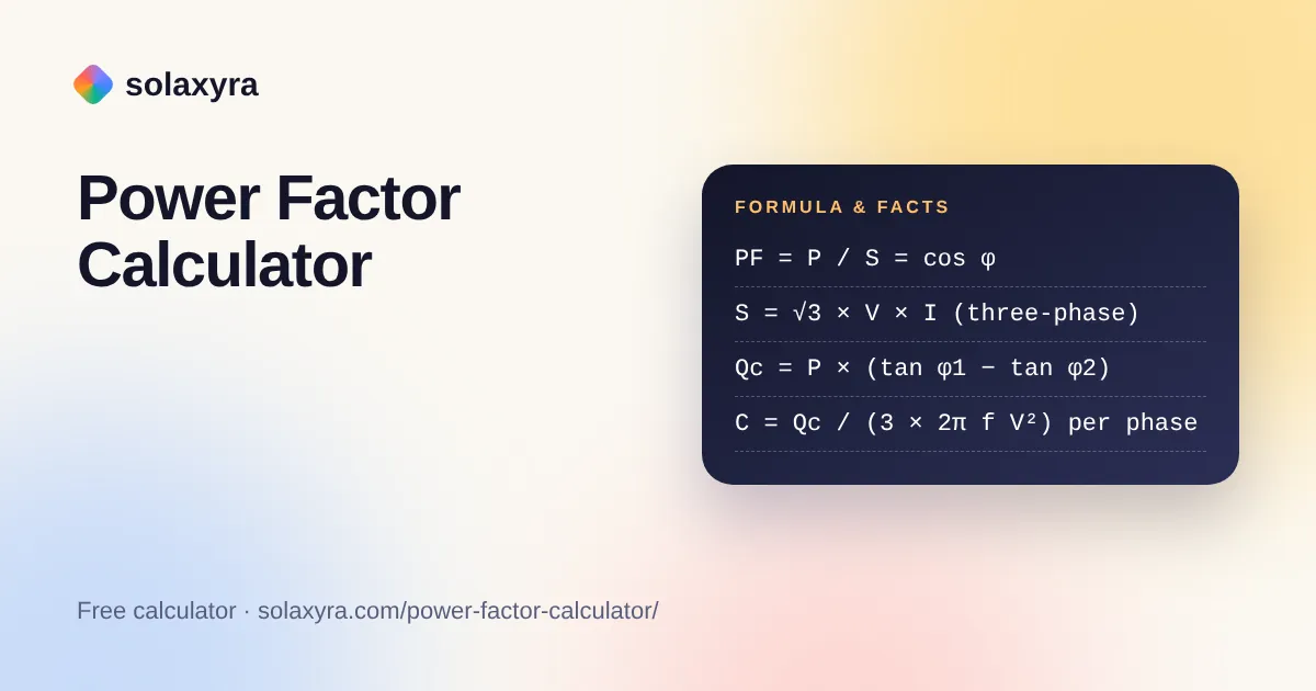
PF = P / S
This power factor calculator works out the power factor, phase angle and reactive power (kVAr) of a single-phase or three-phase load, then sizes the correction capacitor needed to reach a target, with 50 Hz and 400 V defaults for the UK, Ireland and the rest of Europe. Enter meter readings in kW and kVA, or measured volts, amps and watts.
Quick answer: Power factor is real power divided by apparent power, PF = kW / kVA. With volts and amps, apparent power is V × I on single-phase or 1.732 × V × I on three-phase. A 36 kW load drawing 48 kVA has a power factor of 0.75 and needs about 19.9 kVAr of capacitors to reach 0.95.
What Is a Power Factor Calculator?
A power factor calculator is a tool that divides the real power a load uses by the apparent power the supply has to deliver, and turns the result into the angle, reactive power and capacitor size behind it. In plain words: power factor equals kilowatts divided by kilovolt-amperes, and the missing part of the triangle is reactive power in kVAr.
The three quantities form a right-angled triangle. Real power P (kW) does useful work, reactive power Q (kVAr) shuttles back and forth to build the magnetic fields in motors and transformers, and apparent power S (kVA) is the combination the cables and transformer must carry. They are linked by S² = P² + Q². For steady sinusoidal voltage and current, the power factor equals the cosine of the phase angle between them, so PF = P / S = cos φ.
- Single-phase apparent power: S = V × I
- Three-phase apparent power: S = √3 × V(line to line) × I, where √3 is about 1.732
- Reactive power: Q = √(S² − P²), or Q = P × tan φ
- Capacitor needed: Qc = P × (tan φ1 − tan φ2), where φ1 is the present angle and φ2 the target
How Do You Use the Power Factor Calculator?
- Choose what you know: kW and kVA readings from a meter or power analyser, or volts, amps and watts measured on the circuit.
- Select single-phase or three-phase. The voltage switches between 230 V and 400 V, the nominal values in the UK and EU.
- Check the supply frequency. Leave it at 50 Hz in Europe; choose 60 Hz for North American equipment.
- Set a target power factor for correction. 0.95 is a common goal; 1.00 shows the full reactive power.
- Read the power factor, phase angle, kVAr, line current and capacitor size. Open Formula and breakdown to see every step with your numbers.
- Use Copy result to paste the figures into a quote, report or email to your electrician.
If you only need to convert between kVA and kW at a known power factor, the kVA to kW converter is quicker, and the three-phase power calculator handles line and phase voltages in more detail.
What Is a Good Power Factor?
A power factor of 0.95 or above is generally regarded as good, because commercial electricity contracts that charge for poor power factor typically set their limit somewhere between 0.9 and 0.95. A purely resistive load such as a kettle or immersion heater sits at 1.0. Induction motors, welders, older fluorescent lighting and lightly loaded transformers pull it down because they draw magnetising current that does no useful work.
A low power factor matters because the cables, switchgear and transformer must carry the full apparent current, not just the useful part. At 0.75, a supply carries a third more current than the same kW load at 1.0. That extra current raises resistive losses, adds to voltage drop and can use up spare capacity on a site supply that would otherwise accept more equipment. If you are checking cable runs after a change in load, pair this tool with the voltage drop calculator.
How Do You Calculate Power Factor from Volts, Amps and Watts?
Multiply volts by amps to get apparent power, multiply again by 1.732 on a three-phase supply, then divide the measured watts by that figure. For example, a single-phase compressor drawing 10 A at 230 V while a power meter shows 1,800 W has S = 2,300 VA, so its power factor is 1,800 / 2,300 = 0.78.
The watts must come from a true power meter or analyser. A clamp meter on its own gives current but not real power, and multiplying volts by amps on its own only ever gives apparent power. Take both readings at the same time, because the power factor of a motor changes with load. A motor running lightly loaded usually shows a much lower figure than the same motor at full load.
How Much Capacitance Do You Need to Correct Power Factor?
The capacitor rating in kVAr equals the real power in kW multiplied by the difference between the tangents of the present and target phase angles: Qc = P × (tan φ1 − tan φ2). Raising a 40 kW load from 0.80 to 0.95 needs 40 × (0.750 − 0.329) = 16.9 kVAr.
To turn kVAr into microfarads, use the fact that a capacitor’s reactance is 1 / (2π × f × C), so a single-phase capacitor across voltage V supplies Q = 2π × f × C × V². Rearranged, C = Q / (2π × f × V²). For a three-phase bank connected in delta, each of the three capacitors sees the full line voltage and supplies a third of the total, so the calculator shows C per phase = Qc / (3 × 2π × f × V²). Frequency matters: the same kVAr needs about 20% more capacitance at 50 Hz than at 60 Hz, which is why tools that assume 60 Hz undersize capacitors for European sites.
Capacitor banks store charge, can stay live after isolation and can resonate with harmonic currents from variable speed drives, LED drivers and inverters. Correction equipment must be selected, installed and tested by a qualified electrician or power quality engineer. In the UK the installation must meet BS 7671; elsewhere, follow the local wiring rules.
What Is the Difference Between Displacement and True Power Factor?
Displacement power factor comes only from the phase shift between voltage and current, while true power factor also includes the effect of distorted, non-sinusoidal current, and equals displacement power factor multiplied by distortion power factor. Motors mainly cause displacement; switch-mode power supplies, chargers and drives mainly cause distortion.
Capacitors correct the displacement part only. If a site has heavy harmonic distortion, adding capacitors alone may not raise the true power factor much and can make resonance worse, so a harmonic survey comes first. When you enter kW and kVA from a power analyser that measures true RMS values, this calculator returns the true power factor; the capacitor sizing assumes the shortfall is mainly displacement.
Power Factor Reference Table
Use this table to sense-check results. Values are calculated from the formulas above, with the last column showing the kVAr of capacitors needed per kW of load to reach 0.95.
| Power factor | Phase angle | kVAr per kW (tan φ) | kVA per kW (1 / PF) | kVAr per kW to reach 0.95 |
|---|---|---|---|---|
| 0.60 | 53.1° | 1.333 | 1.667 | 1.005 |
| 0.70 | 45.6° | 1.020 | 1.429 | 0.692 |
| 0.75 | 41.4° | 0.882 | 1.333 | 0.553 |
| 0.80 | 36.9° | 0.750 | 1.250 | 0.421 |
| 0.85 | 31.8° | 0.620 | 1.176 | 0.291 |
| 0.90 | 25.8° | 0.484 | 1.111 | 0.156 |
| 0.95 | 18.2° | 0.329 | 1.053 | 0 |
| 1.00 | 0.0° | 0 | 1.000 | 0 |
Worked Example: A Three-Phase Workshop in Bristol
Priya runs a joinery workshop in Bristol on a 400 V three-phase supply. Her power analyser shows 36 kW and 48 kVA while the saws and extractor are running.
- Power factor: 36 / 48 = 0.75, a phase angle of 41.4°.
- Reactive power: √(48² − 36²) = 31.7 kVAr.
- Line current: 48,000 / (1.732 × 400) = 69.3 A.
- Capacitor to reach 0.95: 36 × (0.882 − 0.329) = 19.9 kVAr.
- Capacitance per phase, delta connected at 50 Hz: 19,916 / (3 × 314.16 × 400²) = 132 µF.
- After correction: S falls to 36 / 0.95 = 37.9 kVA and the line current to 54.7 A, about 21% lower.
The real power, and therefore the kWh on her bill, stays the same at 36 kW. What changes is the current in her cables and any reactive power charge in her business contract. Priya asks her electrician to check harmonics from the dust extractor’s drive and to quote an automatic capacitor bank sized to these readings.
Does Power Factor Matter for Homes?
For most households in Great Britain power factor does not change the bill, because domestic electricity is charged per kWh of real energy plus a daily standing charge, as the Ofgem price cap figures show. It still matters when sizing a generator, inverter or UPS rated in VA or kVA, because those ratings cover apparent power. The kW to kVA calculator helps with that sizing.
Frequently Asked Questions
What is the formula for power factor?
Power factor equals real power divided by apparent power, PF = P / S, using kW and kVA. For purely sinusoidal voltage and current it also equals the cosine of the phase angle between them, so a 36.9 degree lag gives a power factor of 0.80.
Can power factor be greater than 1?
No. Real power can never exceed apparent power, so power factor ranges from 0 to 1. If a calculation gives more than 1, the kW and kVA readings were probably taken at different times, in different units, or with a meter that does not measure true RMS values.
What is the difference between leading and lagging power factor?
A lagging power factor means current lags voltage, which happens with inductive loads such as motors and transformers. A leading power factor means current leads voltage, which happens with capacitive loads or over-corrected capacitor banks. Most commercial and industrial sites run lagging.
How do I calculate kVAr from kW and power factor?
Multiply kW by the tangent of the phase angle: kVAr = kW × tan(arccos PF). A 50 kW load at a power factor of 0.80 has tan φ = 0.75, so it draws 37.5 kVAr of reactive power alongside its real power.
What power factor do electricity suppliers require?
Suppliers and network operators that charge commercial customers for poor power factor typically set the limit between 0.9 and 0.95. The exact threshold and charge depend on your contract and network area, so check your business tariff or ask your supplier for the reactive power terms.
Is a power factor of 0.8 good or bad?
A power factor of 0.8 is below the usual 0.9 to 0.95 target, so it is generally considered poor for a commercial site. The supply carries 25% more current than the useful load needs, and a business tariff may add reactive power charges.
Checked October 2026 by the Solaxyra Editorial Team. Sources: Wikipedia, Power factor, Wikipedia, Electrical reactance, Wikipedia, Mains electricity by country, Ofgem, energy price cap October to December 2026.